Sensice Innovation
Remote Ice Detection
Sensice produces ice detectors that identifies the road surface state as being one of dry, wet or icy.
Black Ice Detection
Sensice produces ice detectors that identifies the road surface state as being one of dry, wet or icy. It is further able to tell road surfaces covered by clear ice, often called black ice, from dry, wet or snowy roads and roads covered by sleet or clear ice with a layer of water on top of the ice. One of the most useful benefits is its ability to detect black ice, which often is near invisible to the human eye. The detectors sense presence of ice over an extended area, typically extending a width corresponding to a road lane.
Applications
Sensice' instruments are often used for supervision of the road surface state. They may also be used for detection of ice on runways, bridges or wind power plant turbine wings. The instruments may also be used for meteorological purposes or in industrial applications.
Technology & Advantages
Our ice detectors are based on infrared spectroscopy, which is the only viable technique. Sensice' spectroscopic instruments emit a beam of infrared light that hits an extended area. Light is partially absorbed by ice or water on that area, and light reflected back to the detector is sensed. Presence or absence of ice or water is then calculated using the optical properties of the retro reflected infrared light.
Sensice' ice detectors use an innovative new design that allows a superior price/performance ratio. As compared to ordinary laser based systems the purchase cost is reduced. Lasers have a limited life span, demanding regular replacement, which additionally gives competing instruments a higher maintenance cost. Sensice' ice detectors are not laser based, giving a significantly lower maintenance cost.
View details »Mechanical Properties
Size and Weight
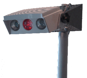
The instrument is 182mm x 154mm x 82mm (width x length x height) and weighs 3.1 kg. Mounted, the instrument and its holder extend a maximum of 260mm from the pole.The holder has a height at its base of 120mm. With holder, the total weight is 4.4kg.
Tiltable holder
The holder is provided with a pair of clamps for grasping around vertical poles with a diametre in the interval 35-50mm. The holder has two knobs that are tightened to hold the direction of the instrument fixed. A safety catch wire is attached to the holder in order to prevent it from free falling if dropped during mounting. The safety catch wire should be securely attached during mounting and remain attached.
Mounting
If the holder is used, it should be attached to a rigid pole or similar.
Optical Properties
Detection Range
Recommended detection range for the ice detector is in the range 3m-15m. The maximum detection range is under optimal circumstances larger, but use at detection ranges exceeding 25m is advised against.
Response Time
The instrument continuously assesses surface properties and transmit measurement results once per second, representing an estimate of the surface properies during the last one second up to transmission of data.
Sunlight Glare
Reflected sunlight or intense artificial lighting reflected directly into the instrument may cause temporary saturation of the photo detectors, rendering it unable to make measurements. Glare error messages are then transmitted by the instrument. Directing the instrument directly towards the sun may irreversibly damage the photo detectors and it then has to be returned to the supplier for replacement of the main circuit board.
Blocking of the Beam
Obviously, the light beam is blocked by interfering objects in the beam, and this must be considered when mounting the instrument. The instrument must have a fully clear view of the detection area. If an object blocking the view is present, ice and water on this object will be detected. Objects rapidly passing through the beam will give rise to a phase error, which is transmitted by the instrument. In case of a phase error, no surface data are available. Within one second of the passing object having left the field of view, a new, reliable measurement is presented. Occasionally, customers may prefer mounting the detector behind a protective screen or window. It is then necessary that the window is fully transparent in the near infrared wavelength range. Obviously, if the window or screen is covered by a layer of ice or water, the detector will present measurements partially representing this ice or water layer.
Detection Area
The outgoing light beam has a divergence of 12°, giving a detection area with a width of 3m at a distance of 14m. This is adapted to correspond to a typical road lane width. Detecting at a shorter or longer distance, gives a correspondingly smaller or larger detection area.
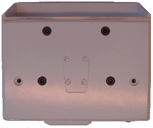
Bottom surfaceLamp Exchange Port
An extended lifetime Xe incandescent lamp is used as light source and this has to be replaced regularly. Replacement is performed by loosening the screws on the lamp exchange port, shown at the centre of the illustration above. The lamp socket is then accessible, making lamp replacement easy. Do note that the lamp exchange port then has to be properly repositioned and screws sufficiently tightened, so that the instrument remains waterproof.
Resistance to Environmental Influences
Precipitation Immunity
The interior parts of the instrument are IP67 waterproof. It is provided with a front screen extending above and in front of the apertures which protects it against direct precipitation. Typically, the instrument is angled downwards, which further protects the front apertures from precipitation.
Temperature range
The instrument is functional in the temperature range of -30°C to +40°C. Acceptable storage temperatures extend to +100°C.
Dirt build up on apertures
The front screen prevents against dirt falling down from above, and mounting the instrument at a sufficient height above the ground reduces the risk of splatter from passing vehicles. Regular cleaning of the front apertures may be necessary.
Dew and frost
31W of heat is emitted primarily via convection from the cooling fins on top of the instrument. At use, this heats the instrument and prevents build up of dew or frost. When the instrument has been disconnected from its power source, frost or dew may remain on the front apertures for a short while after being powered on again.
Electrical Properties
Power Supply
The instrument is powered by 12V±0.3V DC and draws 2.6A. Current is supplied with an IP67 waterproof Binder series 768 connector. Power on is indicated by an LED on the rear side of the instrument.
Communication Interface
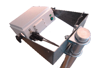
Measurement results are transmitted via RS232 and the series communication interface is bidirectional for reception of control instructions. The RS232 interface uses 57600 baud, 8 data bits, one stop bit and no parity. Measurement results are transmitted from the instrument once per second using a proprietary protocol. A 9 pin IP67 waterproof LTW D-sub connector is used, shown at the lower right side in the image.
Reset
The instrument is provided with a reset button, visible on the lower left side of the image below. Software controlled reset via RS232 is also available. Rear Side
Ports not intended for customer use
A lid, shown at the centre of the image above, prohibits access to further ports that are not intended for normal customer use. The lid should not be removed. The instrument is calibrated at production for optimal performance at ordinary use. It may be recalibrated using a switch behind the lid, but if incorrectly done it may reversibly affect performance negatively and this is strongly advised against.
Interfacing the Instrument
Test Interface
The instruments are not provided with an internal or external display, indicator or power supply. For test purposes, raw data output from the instrument may be viewed by directly connecting the RS232 port to a laptop using Putty, Hyperterminal or similar. Raw data is obviously not usable for any purpose other than simple tests and is not normally used.
Interfacing to a Local Display
Sensice' instruments are easily connected to any selected separate display for viewing. The customer has to transform the raw data to the required presentation form in a desired language. Writing code for this transformation takes little effort for a qualified engineering department.
Interfacing for Remote Viewing
Using external converters, the measurement results may be transmitted for viewing at a remote terminal.
Business-to-Business
Sensice' ice detectors are availiable to companies, government offices, research institutes and corresponding organizations.Contact Information
Adress:
Sensice Strandbergsgatan 61
112 51 Stockholm
Sweden
Email: inquiries@sensice.com
Phone +46 (0)8 339670
© Sensice Innovation 2015